Fully-Loaded Geek

A site containing all things geeky

  • Projects
    • Red/Green LED Matrix 5x5x5
    • Automation Project
    • RC Pontoon Boat
  • Tutorials
    • How to fly Google Earth Flight Simulator with an Arduino joystick
    • Songs on an Arduino
  • Photography
  • About

RGB LED Cube Part 1

Posted by madjako77 on May 25, 2014
Posted in: Uncategorized. Tagged: 328p, Accelerometer, Arduino, Atmega328p, Circuit, Circuit Design, Gyroscope, LED, LED Cube, OSH Park, SD, Shift-bit registers, Unity, XBee. Leave a comment

This project is a large design improvement over my previous RG LED cube design. These improvements include an extra LED color, custom control circuitry, and a large designer improvement. This project is a joint operation between a good friend, Sam and myself.

Since the cube has an extra color per LED, it will increase the number of color combinations making much more diverse shows. In practice, distinct light mixtures are most effective in shows, therefore with 2 colors (Red/Green), the available colors for the show are Red, Red-Green, and Green.

2Color

By adding another color (Blue), the available colors more than doubles to Red, Orange, Green, Teal, Blue, Purple, and White. Obviously more colors is better, but more colors means more complicated control circuitry.

 3Color

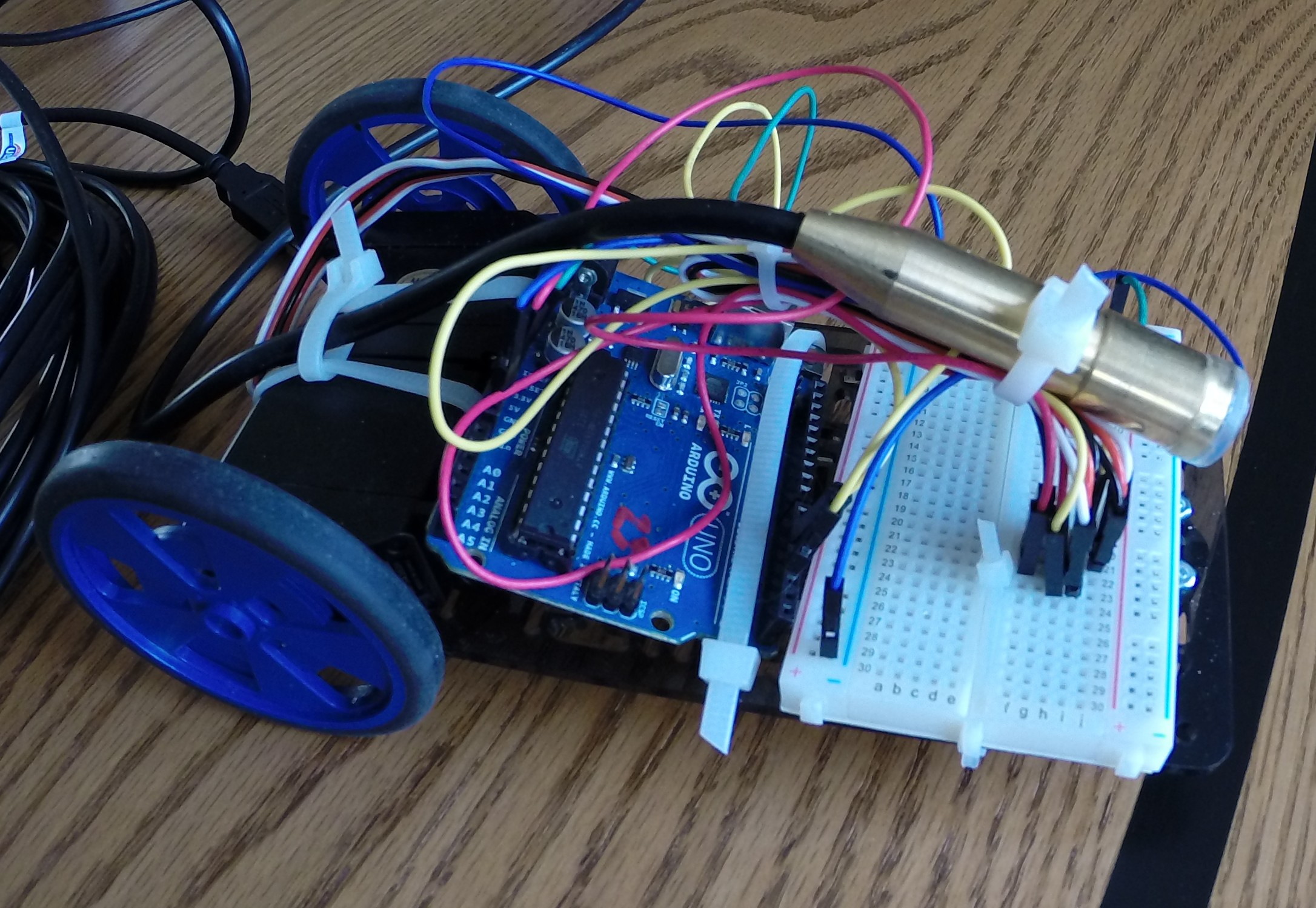
The amount of circuitry required to control this cube is much larger than the previous iteration, and the previous iteration’s circuitry was minimalistic. To remedy this, a custom circuit has been created with this application in mind and was printed through OSH Park. The circuit uses an Arduino Uno chip, the Atmega 328p, which can be programmed using the Arduino environment. The circuit contains shift-bit registers to reduce the amount of processor pins needed to control the lights. The circuit can read to and write from an SD card to store and play shows, it can interface with an accelerometer and gyroscope chip to receive positional information, and it can communicate using an XBee wireless serial communication module allowing remote operation and programming. The circuit uses a simple linear drop regulator to regulate a large range of voltages down to 5V. This supplies the processor and the LEDs with power. The board also contains a number of buttons for control input and a power switch. The circuit works well, but the circuit is only part of the system. To light the LEDs, a controller program and a show designer are needed.

Photo (3 of 2)

Photo (4 of 2)

For the designer application, I have chosen to design a program to display a three dimensional view of the LED cube instead of a 2D layer-by-layer designer used in the last iteration. This display will be used to create and view shows in a simulated environment. The initial target environment I have chosen is Unity. For those who don’t already know, Unity is a game development engine which allows rapid game and 2D/3D application design. I plan on using Unity for two reasons: it automates a large amount of 3D programming and will allow me to branch into 3D gaming very quickly (with the possibility of Oculus Rift virtual reality development).

Capture

The design picture shown above is currently a bit hard to look at, however, it will be greatly improved. At this point clicking the LEDs will toggle their color. The view can be rotated left, right, up, and down as well as zoomed in and out. Eventually a GUI will be constructed around the cube for the easy development and saving/loading of shows.

The controller program used to run the shows has not been fully developed and will take shape as the designer is completed.

As this project is still in progress, I have not been able to produce any intriguing demonstrations, however, keep checking here for more updates. I am going to begin detailing the process of game creation and 3D application design in Unity as I learn it.

How to create an animation in GIMP

Posted by madjako77 on May 23, 2014
Posted in: Uncategorized. Tagged: animation, banner ad, GIMP, How-To, Howto, Jamie McFarlane, Privateer Tales, Rookie Privateer. 1 Comment

animsmall

Recently, I was tasked with creating a banner ad for Jamie McFarlane’s book. He sent me some of the graphics for his book and I came up with this little ad. I wanted to share my final product and a general overview of the process required to make an animation in GIMP. (If animation does not show up, click here)

First, I positioned all the text and images of the background the way I wanted them. Then I created a layer in GIMP for each part of the animation. Because each frame is simply a combination of layers, I was able to show and hide the text when the time was right by clicking the show/hide button in GIMP.

1

To generate the frames, I systematically went through and exported pngs of each frame of the animation showing and hiding the correct layers to produce the desired frame.

2

After all the frames were generated, I imported them into a new gimp project and arranged them with the last frame in the animation as the highest layer. Then to produce the best result, I used custom timing for each frame. This is accomplished by putting the delay time after the layer name, as an example “Frame1” delayed for 100 milliseconds would be “Frame1(100ms)”.

3

After all the layers have been positioned and timed, you can go to File -> Export, choosing a filename ending in .gif such as animation.gif. This will bring up the gif options. From there you can set the default time (only used when you don’t specify it), a few other options, and the option to loop the animation. After clicking export, the gif will be generated.

4

Thanks for reading. Feel free to check out my other posts as well as Jamie McFarlane’s site/book (you can click the ad).

Up and coming Sci-Fi Fiction Writer

Posted by madjako77 on May 16, 2014
Posted in: Uncategorized. Tagged: Book, Fantasy, Jamie McFarlane, Privateer Tales, Privateer Tales #1, Rookie Privateer, Sci-Fi, Writer. Leave a comment

Rookie Privateer Part 1

I just recently read a book by an up and coming self-published author, Jamie McFarlane, that just released his first book in his series, Rookie Privateer. I absolutely love this imaginative book. I was drawn in immediately and love the story line all the way through. The characters are relatable, quirky, and fun to follow. I would recommend this book to anyone who loves sci-fi. Plus I have already heard rumors about Jamie releasing a second book in the Rookie Privateer series. I always love a good series with the great potential for more storyline!

Please help this awesome author and intriguing series by spreading the word!

I can’t wait for Jamie McFarlane’s next book in the Rookie Privateer series.

Arduino Object Following

Posted by madjako77 on May 11, 2014
Posted in: Uncategorized. Tagged: Arduino, Education, Embedded Systems, image processing, Object Detection, OpenCV. Leave a comment

Robot

As an honor’s project for my Embedded System class, I was tasked with using an Arduino to track an object/line with a camera sensor. I worked for a while trying to achieve this goal, but found the Arduino to be very lacking when it comes to image processing. Instead I was able to use a USB camera and OpenCV to detect an object and then transmit enough information for the Arduino to follow the object. I haven’t made a video of the project in operation, but here are two images to show you what I’ve done.

Frame

Thresh

The first image shows the camera view with an overlay of the object’s center position. The second image is the first image with an HSV threshold applied. To get the object’s center position, I used some built-in functions dealing with image moments. The center position is processed and the computer determines the direction the robot must move and then sends this to the Arduino through the serial port. The Arduino then controls the motors in response to these messages.

The robot follows the object fairly well and responds as if it is a curious animal that is afraid of the object getting too close. This project has taught me that image processing is much more complex and should never be attempted on the Arduino.

Raven Robot Demonstration

Posted by madjako77 on May 10, 2014
Posted in: Uncategorized. Tagged: Arduino, Education, Embedded Systems, Line Following, Robot. Leave a comment

For the final group project in my Embedded Systems class this year, we were tasked with building a robot that could navigate through a simple arena.

Our robot, Raven (Robotic Arduino Vehicle with Enviable Nerves), had to start at one end of the arena and make it to the other end of the arena while another robot did the same. The arena had a black line running through the middle and some obstacles blocking our way. We used two IR light sensors, one proximity sensor, and two bump sensors to detect our environment. We used continuous rotation servos and an Arduino to tie it all together.

Here is a video demonstrating Raven’s logic.

Raven navigated the arena by following the line until her bump sensors were hit. Then Raven would use her proximity sensor to avoid the block and get back on the line. This would then be repeated until we got stuck or made it successfully out of the arena.

Raven operated quite well given the simplicity of her programming and came in second place in the final competition. We couldn’t be more proud of her.

Special thanks to Trudy and Patrick for the great partnership.

Arduino Line Following Robot

Posted by madjako77 on March 25, 2014
Posted in: Uncategorized. Tagged: Arduino, Autonomous, Line Following, Robot. Leave a comment

For my embedded systems class this semester, our first project was to create a line following robot using an Arduino, two servos, and two IR sensors.

Demonstration:

https://www.youtube.com/watch?v=b374YOKX74I

Stability:

https://www.youtube.com/watch?v=3h2hCDh6TkI


In the videos above, I reset the robot to make sure the light adjustment was accurate. I then allowed the robot to scan the line for even better adjustment. Then I pressed the button to go to mode 1, which then started the motors. The first video shows a working demonstration and the second video shows how difficult it is for the robot to lose its place. While I did not show the robot failing to get back on the line, it is still possible and can be accomplished by smacking it hard enough to move the line out of its turn radius. That being said, the robot should not need to deal with those conditions in practice.

The robot itself is simply two continuous rotation servos, two IR sensors, a button, and an Arduino. The Arduino sketch comprises most of the complexity of the project. The Arduino program used to control the robot can be downloaded below. The program has 4 modules that run. First, a setting module watches for button presses and allows other modules to respond to different modes of operations set by the button. The second module is a thresholder that takes the analog sensor values, takes averages and stores the min and max values. Then the thresholder converts the analog values into a ‘1’ if the sensor detects the line and ‘0’ otherwise. The third module is the transition module, which pays attention to the change of the sensors and will output a value telling the other modules if the robot is moving left or right with respect to the line. The last module controls the motors. The motor is driven given the binary sensor values and the left/right value to determine which way it needs to move. The logic is designed to go forward when the left sensor is on the line and the right sensor is off the line. Any other combination will cause the robot to drive towards the line.

LineFollowingRobot.zip (File –> Download)

Future Improvements:

Most line following robots use a multitude of sensors to increase their ability to detect the line. As an Honor’s project, I will be using a camera instead. This camera is the OV7670 camera module that uses a parallel data port and a subprotocol to the I2C (TWI) protocol to manipulate settings. In the current stage of development, the camera operates at 2.5fps at a resolution of 176 x 144, which will give me the same resolution as if I had 25,344 IR sensors. The hardware implementation of the I2C protocol (Wire library) does not properly communicate with the camera (The speed of 100 kHz is too fast), so I created my own library to run I2C communication manually with a scalable speed. Using this library, the Arduino can communicate with the camera smoothly. Soon I will create an Arduino sketch to save the camera data to an SD card, and a Java program to interpret this raw data and format it into JPEG or BMP.

Stay tuned for more updates on this project.

Posts navigation

Newer Entries →
  • Follow Fully-Loaded Geek on WordPress.com
  • Pages

    • About
    • Photography
    • Projects
      • Red/Green LED Matrix 5x5x5
      • Automation Project
      • RC Pontoon Boat
    • Tutorials
      • How to fly Google Earth Flight Simulator with an Arduino joystick
      • Songs on an Arduino
  • Recent Posts

    • Simple Hard Apple Cider
    • IOT Motion Sensor
    • Cheap, easy to develop IOT devices
    • Fractal Generator
    • NodeMCU
  • Most Viewed Pages

    • Simple Hard Apple Cider
    • IOT Motion Sensor
    • Cheap, easy to develop IOT devices
  • Search

Website Powered by WordPress.com.
Privacy & Cookies: This site uses cookies. By continuing to use this website, you agree to their use.
To find out more, including how to control cookies, see here: Cookie Policy
  • Subscribe Subscribed
    • Fully-Loaded Geek
    • Already have a WordPress.com account? Log in now.
    • Fully-Loaded Geek
    • Subscribe Subscribed
    • Sign up
    • Log in
    • Report this content
    • View site in Reader
    • Manage subscriptions
    • Collapse this bar
 

Loading Comments...